Non Destructive Testing (NDT)
Non Destructive Testing (NDT)
Magnetic particle testing (MPI)
MPT is a fairly simple process with two variations: Wet Magnetic Particle Testing (WMPT) and Dry Magnetic Particle Testing (DMPT). In either one, the process begins by running a magnetic current through the component. Any cracks or defects in the material will interrupt the flow of current and will cause magnetism to spread out from them. This will create a “flux leakage field” at the site of the damage. The second step involves spreading metal particles over the component. If there are any flaws on or near the surface, the flux leakage field will draw the particles to the damage site. This provides a visible indication of the approximate size and shape of the flaw. There are several benefits of MPT compared to other NDE methods. It is highly portable, generally inexpensive, and does not need a stringent pre-cleaning operation. MPT is also one of the best options for detecting fine, shallow surface cracks. It is fast, easy, and will work through thin coatings. Finally, there are few limitations regarding the size/shape of test specimens. Despite its strengths, the method is not without its limits. The material must be ferromagnetic. Likewise, the orientation and strength of the magnetic field is critical. The method only detects surface and near-to-surface defects. Those further down require alternative methods. Large currents are sometimes required to perform this method, thus “burning” of test parts is sometimes possible. In addition, once MPT has been completed, the component must be demagnetized, which can sometimes be difficult.
wet magnetic particle inspection is carried out by mean of florescent magnetic particles and an UV light source, it has an advantage over a dry inspection because the equipment used in this process can quickly and easily spray a uniform layer of particles over the surface of the material or part to be inspected. The magnetic field can be produced by the use of direct current (DC) circuits or by alternating current (AC) circuits. AC circuits produce fields that are confined to the near surface of the test sample and are useful in finding surface cracks. DC circuits provide magnetic fields that penetrate a shallow distance into the test sample and are useful for also finding discontinuities below the surface.
Penetrant testing (PT)
PT is one of the oldest and simplest NDT methods where its earliest versions (using kerosene and oil mixture) dates back to the 19th century. Liquid penetrant inspection is used to detect any surface-connected discontinuities such as cracks from fatigue, quenching, and grinding, as well as fractures, porosity, incomplete fusion, and flaws in joints.
PT is based upon capillary action, where low surface tension fluid penetrates into clean and dry surface-breaking discontinuities. Penetrant may be applied to the test component by dipping, spraying, or brushing. After adequate penetration time has been allowed, the excess penetrant is removed, a developer is applied. The developer helps to draw penetrant out of the flaw where an invisible indication becomes visible to the inspector. Inspection is performed under ultraviolet or white light, depending upon the type of dye used - fluorescent or nonfluorescent (visible).
Visual Testing (VT)
Visual inspection of welding can often be the easiest to perform and is usually the least expensive to conduct. If carried out correctly, this type of inspection can often be an extremely effective method of maintaining acceptable welding quality and preventing welding problems. There are many areas within the welding operation that can be verified and evaluated by this method of inspection.
When designing an inspection plan, we need to establish the most appropriate areas to apply our inspection. We need to consider the possibility of preventing welding related problems, rather than finding problems which may have already occurred. Non- destructive testing (NDT), which is typically used for the inspection of completed welds, is usually designed and conducted to find welding problems after the fact, when the weld is completed. Visual inspection can often be utilized to prevent welding problems from happening in the first place. The welding inspection function is often divided into three areas. First, and often the least utilized, is pre-weld inspection. This type of inspection can often provide us the opportunity to detect and correct unacceptable conditions before they develop into actual welding problems. Second, inspection during the welding operation can often prevent problems in the completed weld through verification of the welding conditions and procedural requirements. Third, post-weld visual inspection is a relatively easy method of conducting completed weld quality evaluation. We shall consider each of these inspection stages in more detail.
Pre-Weld Inspection
This inspection is conducted prior to the start of the welding operation. This type of inspection is typically associated with checking the preparation of the welding joint and verification of parameters that would be difficult or impossible to confirm during or after welding. This is the area of inspection where we can best introduce controls that may prevent defective welding. Some areas of pre-weld inspection are joint preparation inspection/pre-weld setup. This may involve the dimensional inspection of root openings. Root openings that are too tight can cause inadequate root penetration. Root openings that are too large can cause over- penetration. Groove weld bevel angles, if too small, may cause lack of fusion, and if too large, can result in distortion of the weld joint from overheating and excessive shrinkage stress. Joint alignment (misalignment of the weld joint) can result in difficulty in producing a sound weld and stress concentration at its location, resulting in a reduction of fatigue life. Plate surface condition and cleanliness, pre-cleaning prior to welding, can often be of extreme importance. Improper or inadequate cleaning can result in unacceptable levels of porosity in the completed weld. Other pre-weld inspections may include preheat verification, temperature and heating method, presence and location of heat treatment monitoring devices, and type and efficacy of gas purging, if applicable.
Pre-weld inspection may also include evaluation and verification of documentation, material certification, filler alloy certification, welder performance qualification, welding procedure qualification, and welder and weld identification, for traceability, if applicable.
Inspection During Welding
This is the inspection that is carried out during the welding operation and is concerned mainly with the requirements of the welding procedure specification (WPS). This inspection includes such items as interpass cleaning methods, interpass temperature control, welding current settings, welding travel speed, shielding gas type, gas flow rate, and welding sequence, if applicable. Also, any environmental conditions that may affect the quality of the weld such as, rain, wind, and extreme temperatures.
Post-Weld Inspection
This inspection typically conducted to verify the integrity of the completed weld. Many non-destructive testing (NDT) methods are used for post-weld inspection. However, even if the weld is to be subjected to NDT, it is normally wise to conduct visual inspection first. One reason for this is that surface discontinuities, which may be detected by visual inspection, can sometimes cause misinterpretation of NDT results or disguise other discontinuities within the body of the weld. The most common welding discontinuities found during visual inspection are conditions such as undersized welds, undercut, overlap, surface cracking, surface porosity, under fill, incomplete root penetration, excessive root penetration, burn through, and excessive reinforcement.
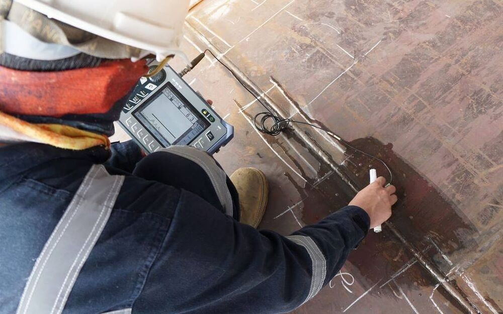
Ultrasonic Testing
Ut thickness gauging
Ultrasonic thickness measurements is a technique using high-frequency sound energy to conduct examinations and obtain thickness measurements. A straight beam is introduced into the test object perpendicular to the surface and round-trip time is measured. Quantifiable information can be gathered for detection of localised or general wall-thickness changes.
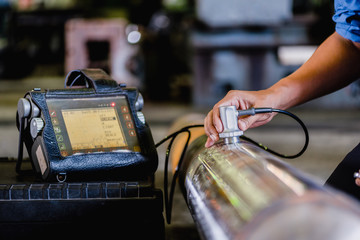
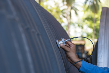
UT shear wave
The ultrasonic shear wave method is a technique which encompasses the use of predetermined angles for the identification of subsurface anomalies not found directly underneath the transducer itself. Indications within a material and or weldement reflect ultrasonic energy back to the transducer, displaying as an A-scan, in which an operator may assess for relevant information concerning component integrity.
The use of ultrasonic shear waves has all the advantages of weld inspection with no inherent safety concerns, no disruption of production due to radiation hazards, near real-time inspection results, and vertical defect sizing for engineering critical assessments. Information can be obtained on surface and subsurface indications detrimental to the end use of components. A high degree of accuracy can be achieved in estimates of discontinuity size, shape and orientation. The technique requires access to only one side of the component, with minimal specimen surface preparation.
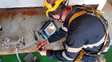
Phased Array UT (PAUT)
Phased Array UT (PAUT) is an advanced nondestructive examination technique that utilizes a set of ultrasonic testing (UT) probes made up of numerous small elements, each of which is pulsed individually with computer-calculated timing. This technique can be used to inspect more complex geometries that are difficult and much slower to inspect with single probes. PAUT can be used to inspect almost any material where traditional UT methods have been utilized, and are often used for weld inspections and crack detection.
Compared to other forms of UT, PAUT has several advantages. PAUT can be conducted more quickly than other forms of UT, often within a fraction of a second. It can easily be used for repeat scans because it has a high degree of repeatability. By emitting beams of multiple different angles sequentially, PAUT is able to create detailed and accurate cross-sections of a part. It is also particularly useful in situations where there is less room for mechanical scanning because it’s able to sweep the beam without moving the probe
Eddy current testing
Eddy current technique is an important electromagnetic non-destructive evaluation technique that is widely used in power, aerospace, petrochemical and other industries for detection of surface cracks and sub-surface damage in components made of metallic materials. Besides, it is also used traditionally for assessing the adequacy of heat treatment of alloys, as eddy currents are sensitive to changes in microstructure and stresses, which alter the electrical conductivity and magnetic permeability of the material. This paper gives a brief account of basic principle, features, applications, limitations of the eddy current technique. It also covers instruments and sensors to enable better appreciation of the technique and its capabilities.
Radiographic Testing (RT)
Radiographic Testing (RT) is a non-destructive examination (NDE) technique that involves the use of either x-rays or gamma rays to view the internal structure of a component. In the oil&gas and petrochemical industry, RT is often used to inspect machinery, such as pressure vessels and valves, to detect for flaws. RT is also used to inspect weld repairs.
Compared to other NDE techniques, radiography has several advantages. It is highly reproducible, can be used on a variety of materials, and the data gathered can be stored for later analysis. Radiography is an effective tool that requires very little surface preparation. Moreover, many radiographic systems are portable, which allows for use in the field and at elevated positions
X-rays and gamma radiation have wavelengths shorter than 100 nanometres (nm). Energy, at these wavelengths, will penetrate solid material. The shorter the wavelength, the greater the penetration. Like visible light, X-rays and Gamma radiation also have a photochemical effect on silver halide and can therefore produce an image on film. Thus, by passing penetrating radiation through an object, and recording the emerging radiation on a film, a two dimensional picture of the differences in thickness or density of the object can be obtained. Hence, flaws in the object can be detected.